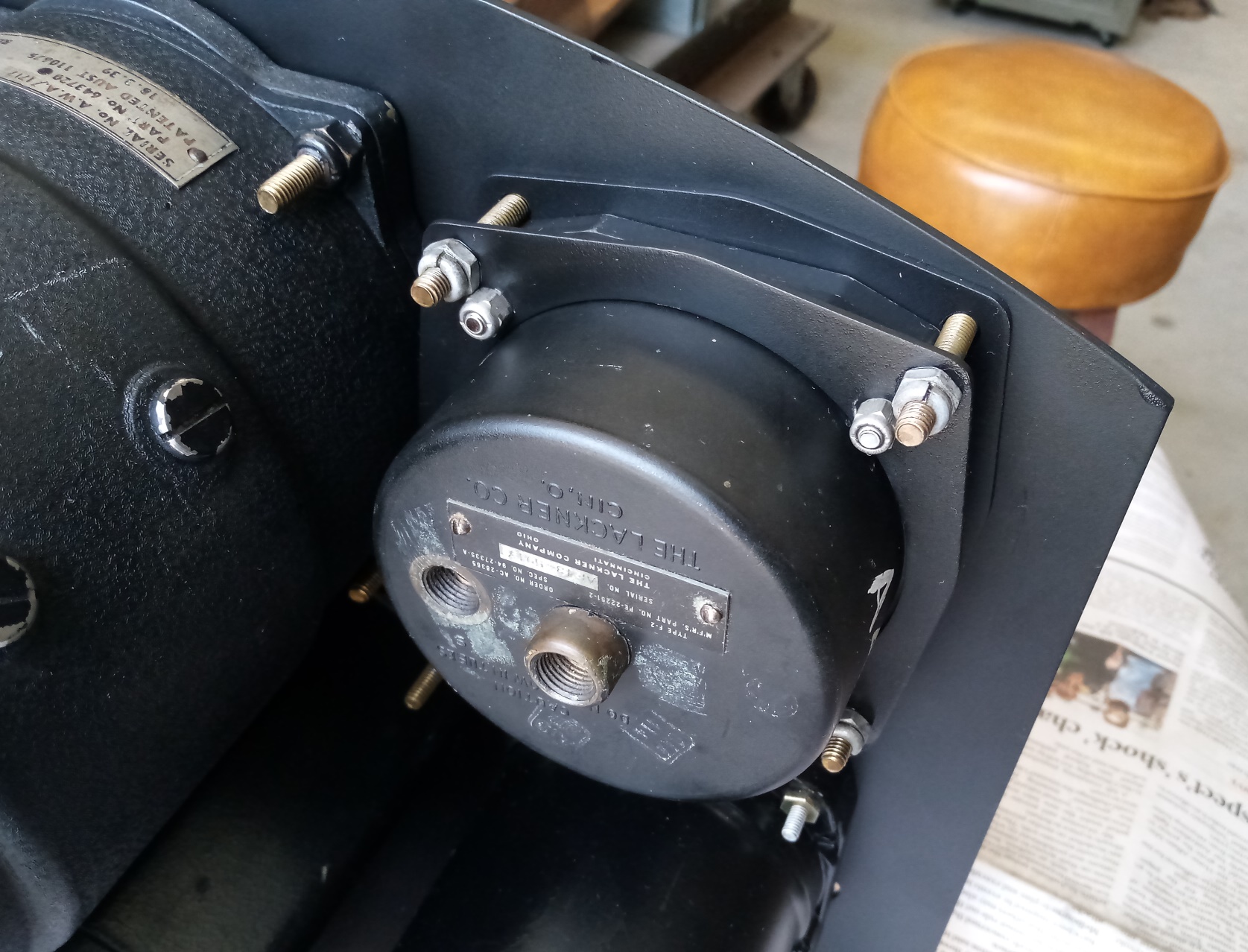
Having a couple of KX generators and Lockheed hydraulic pumps, I figured I would attach these to the SG1/20 gearboxes to see how things come together. The generators for the Vampire Mk.30/31 are actually the KX-B and I haven’t seen any to date at all, let alone had the chance to acquire one. I bought these KXs because I thought they would help the cause one way or another. In addition, the KX was used on the DH.108, attached to the Goblin.
The hydraulic pumps I have aren’t quite right either. They should be Mk.VI, and I have one Mk.7 and one Mk.8. That probably wouldn’t matter of itself, but the orientations of the bodies have different clockings with respect to the mounting holes, presumably variations for specific applications.
Taking the transport covers off the pump locations revealed very clean interiors. Although there is a little black seepage, hopefully this is an indication that the oil seals have been largely effective in keeping the mud from seeping into the interior at the generator, driveshaft and compressor locations.
For two generator and two hydraulic pump locations there is only one quill and no couplings, so there is no check on engagement. However, this quick assembly shows the overall length of the arrangement, how it fits within the engine cowlings, and taught me a little more about the gearboxes and equipment. The trolley/stand I have built has also proven to be a good storage and work arrangement!
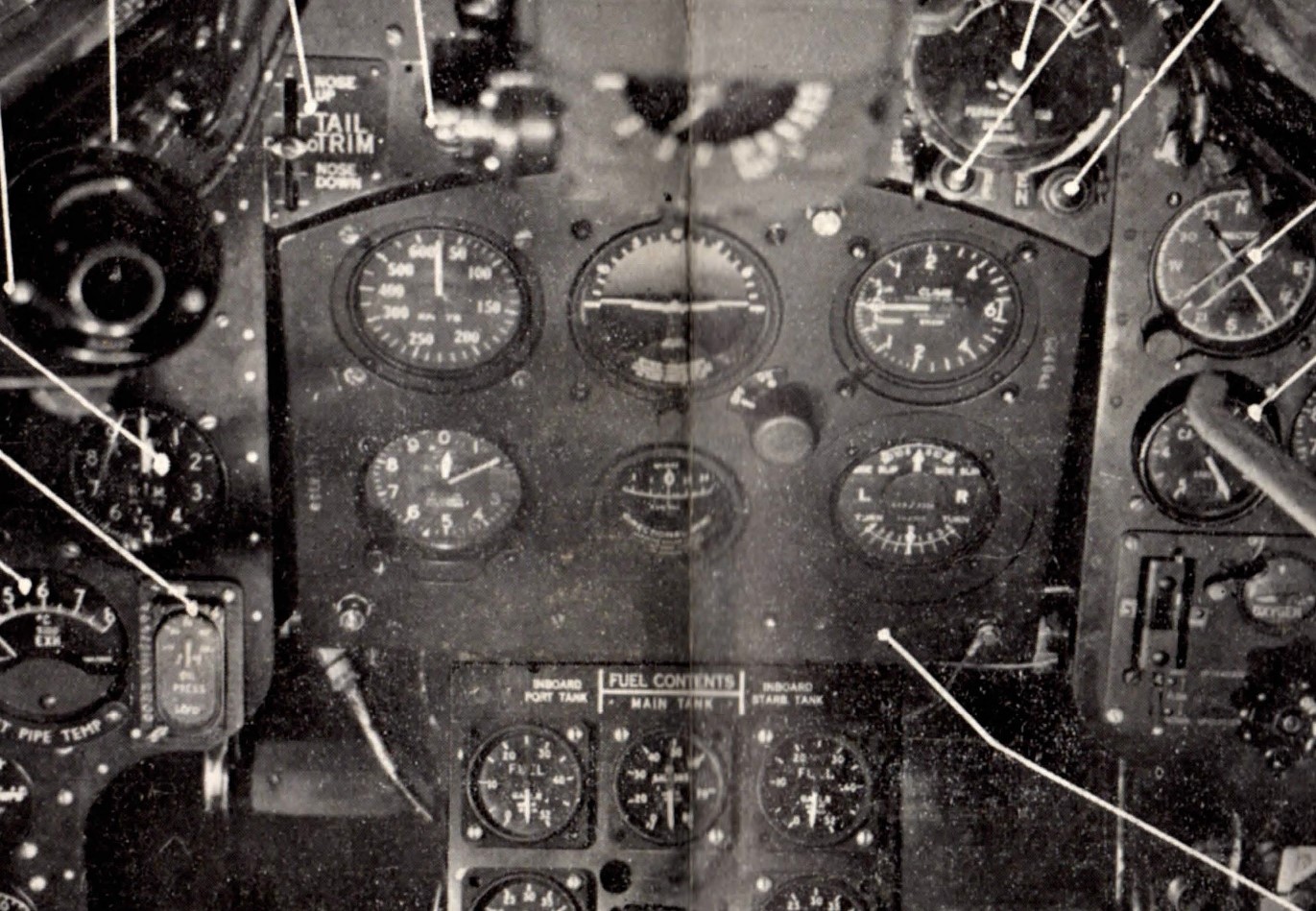
The intent of this panel is to represent the earliest configuration for the Australian-built single-seat Vampires, so I have matched the original schedule of spares as best I can. The original configuration is shown in the Pilot’s Notes and reproduced below.
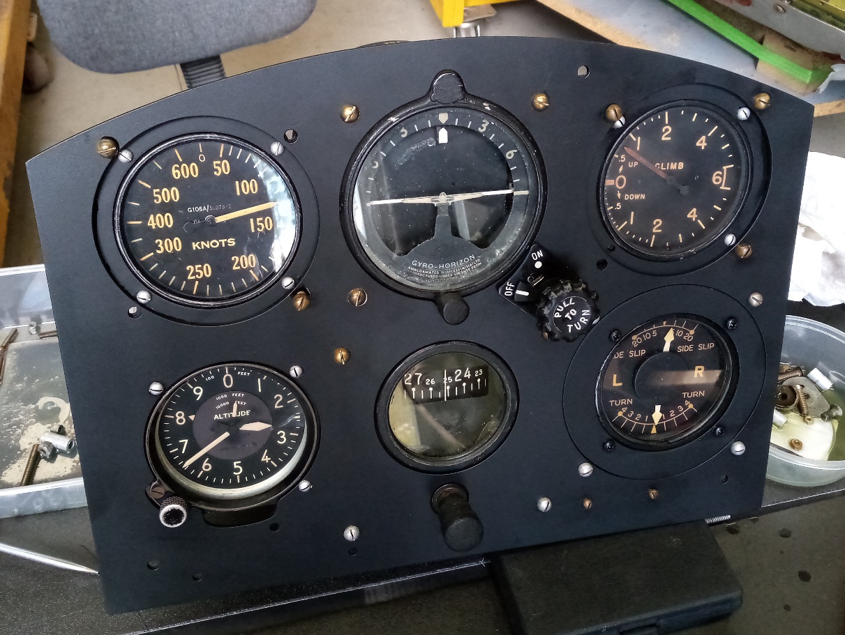
The basic panel is one where I developed the dimensions myself a few years ago. I have since compared it with the original panels discussed in the previous posts, where I can, and am satisfied with the results. Areas are outside of the +/- 0.030” that might apply now for production parts and I can’t say that it would be as accurate as any panel made in the 40s or 50s – who knows! But that’s okay!
The panel is essentially a 6A/760 with a modified altimeter cut-out to accommodate the American C-12. I’ve also replicated the infill and adaptor parts to account for the change in size of the ASI, rate-of-climb and T&S.
While the adaption method for the T&S was straight forward, that for the ASI and ROC was not. This is because the pitch circle diameter (PCD) for the gauge and original panel are quite close. To attach the adaptor plate to the main panel first with screws and nuts would then mean no room for the mounting flange of the gauge. Indeed, for the ASI, the adaptor plate screws themselves come within a whisker of the gauge flange. This means either the adaptor plate needs to be tapped (and therefore needs sufficient thickness to retain the screws) or a second plate with inner and outer screw hole patterns needs to sit on the rear face of the mounting flange. This then has enough room for the nuts of both inner and outer sets of screws to turn, with the second nut in a pair having to be done up with an open spanner.
The ROC is even more complicated still! With the set screw in the bottom left-hand corner, there is no inner screw and the outer screw would need a tapped hole in the adaptor plate (as suggested above), and the screw cannot have any thread protrusion or it will clash with the mounting flange. This is because the flange extends much further out from the set screw location. Access to an original would be nice!
The exact reasoning behind the original design selection of the American gauges is not clear. I have not found any archival correspondence about it. Certainly, it would have been an economic choice to draw upon readily available wartime surplus stocks of new parts. It is not clear if shortages of items from the UK were anticipated, and even if they were, where a choice could be made between dealing with the problems as they arose during production or a design change to avoid the anticipated shortage. Irrespective of shortages, the redesign of the main electrical junction box with circuit breakers (American) in lieu of the original UK arrangement with fuses is clearly about extending a positive functional feature beyond American service aircraft. Items like the C-12 altimeter and C2 rate-of-climb were good choices as they proved to be enduring patterns.