Blind Flying Panels – DH.108 TG283

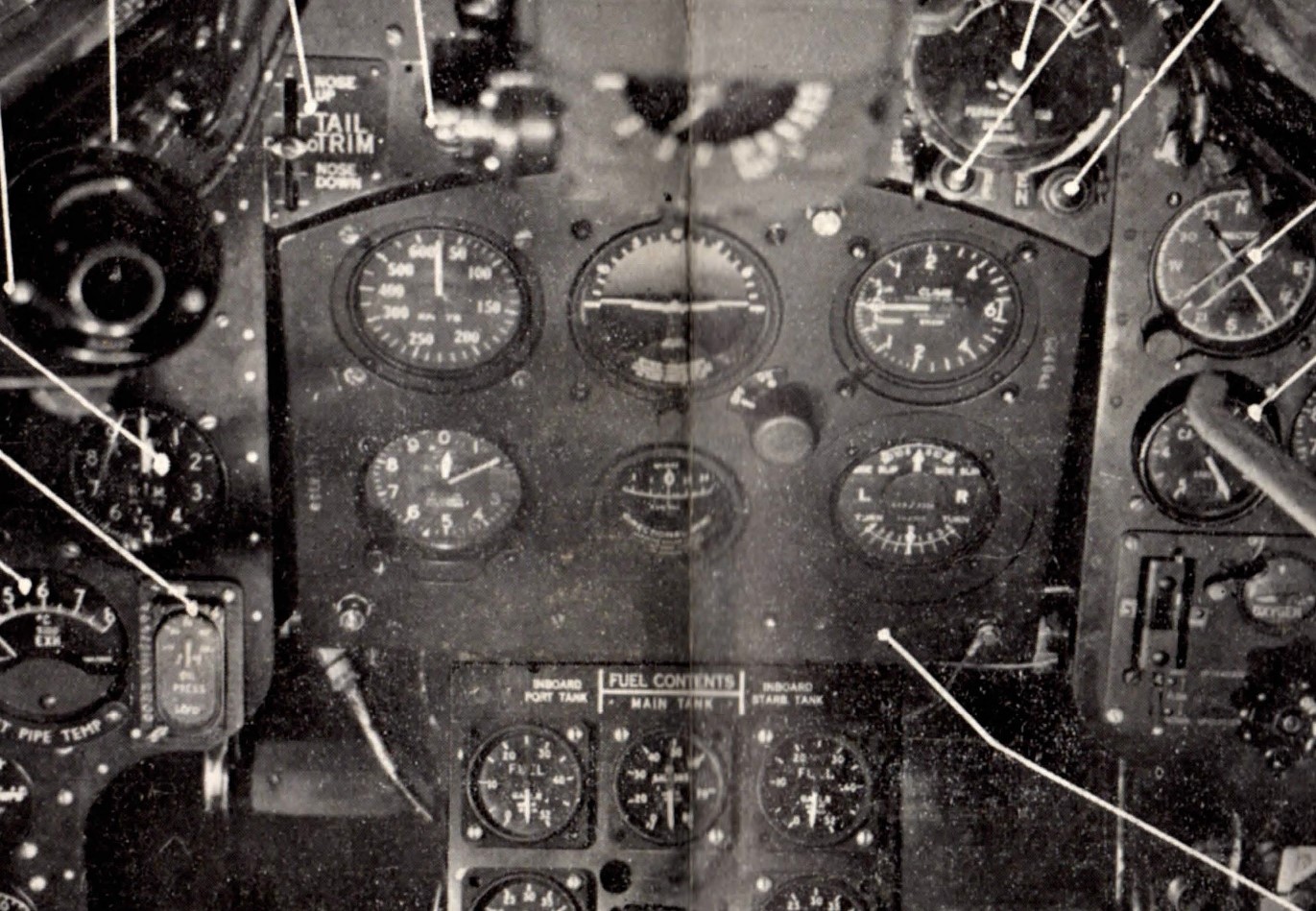
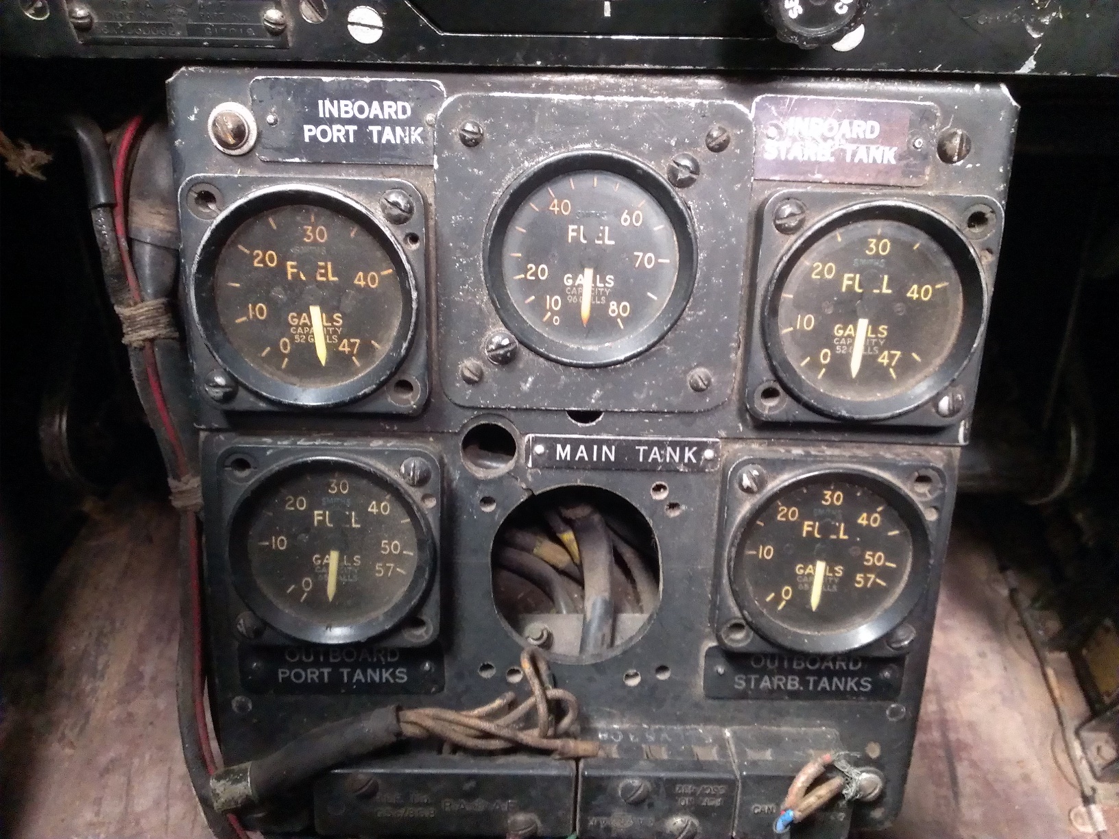
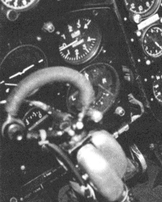
In order to build up a full set of instrument panels to represent DH.108 TG283, I have had to make many assumptions. For the blind flying panel – the set of 6 primary instruments – I have started with what I can see in the published photo of the cockpit (available in Rivas and Matthews1). See the snippet below. This looks like the typical fighters of the time, including the Vampire F.I, which the aircraft was built from.

Blind Flying Panel in the Cockpit of DH.108 TG283

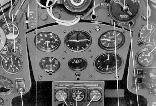
So I have assumed that the aircraft would have retained its original F.I BFP (below, from the AP.4099A Vampire F.I Pilot’s Notes); I have no reason to think that the air speed indicator or altimeter – the two on the left of the BFP – would be anything but standard. TG283 was the aircraft that was built for the low-speed range of the DH.108 flight test program; TG306 and VW120 (the other two DH.108 aircraft) at the high-speed end.

Vampire F.I Blind Flying Panel

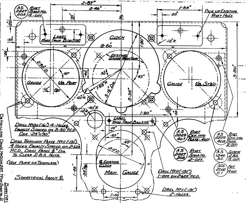
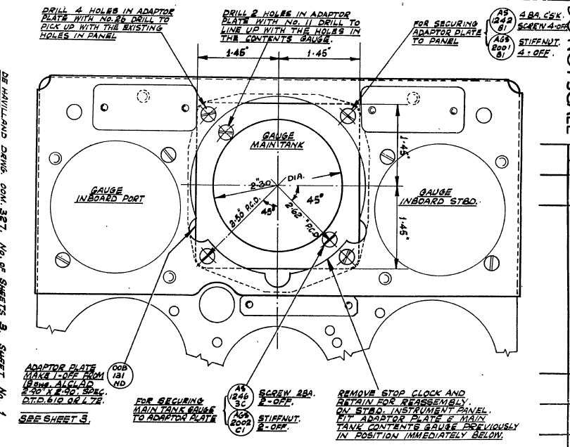
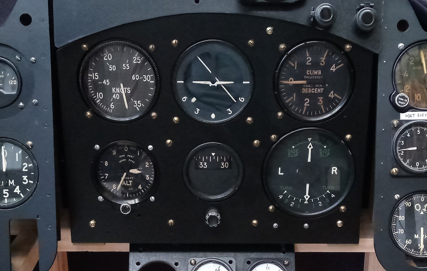
The instruments I have collected together are a reasonable match visually but ideally I would match the gauges fitted at the time. TG283 flew from May 1946 to May 1950. I don’t have the Vampire F.I schedule of spare parts or any drawings of the Mk.I, but I do have a drawing applicable to Vampire Marks 3, 4 (original Vampire Mk.II production designation), 5, 9 and 20 – snippet below. This shows some matches for what I have, but it’s only an indication.

Extract from De Havilland Engineering Drawing B00924

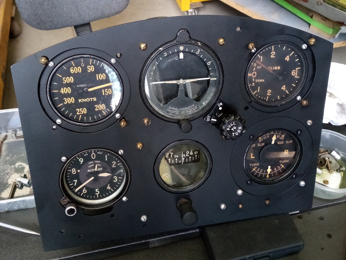
The parts I have installed:

Air Speed Indicator Mk.9H*        6A/1985

Artificial Horizon                           6A/1519

Rate of Climb Mk.IB*                   none

Altimeter Mk.XIVB                        6A/1512

Direction Indicator Mk.IB            6A/1666, Sperry p/n 656557

Turn & Slip                                     6A/1302

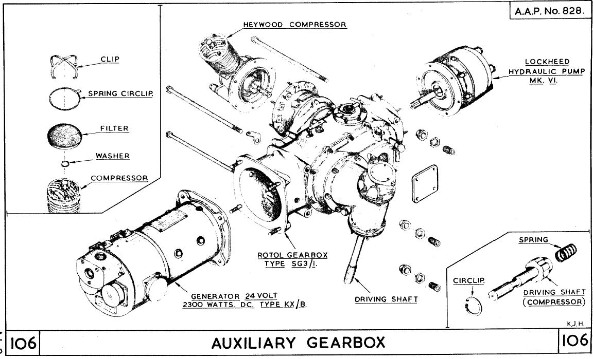
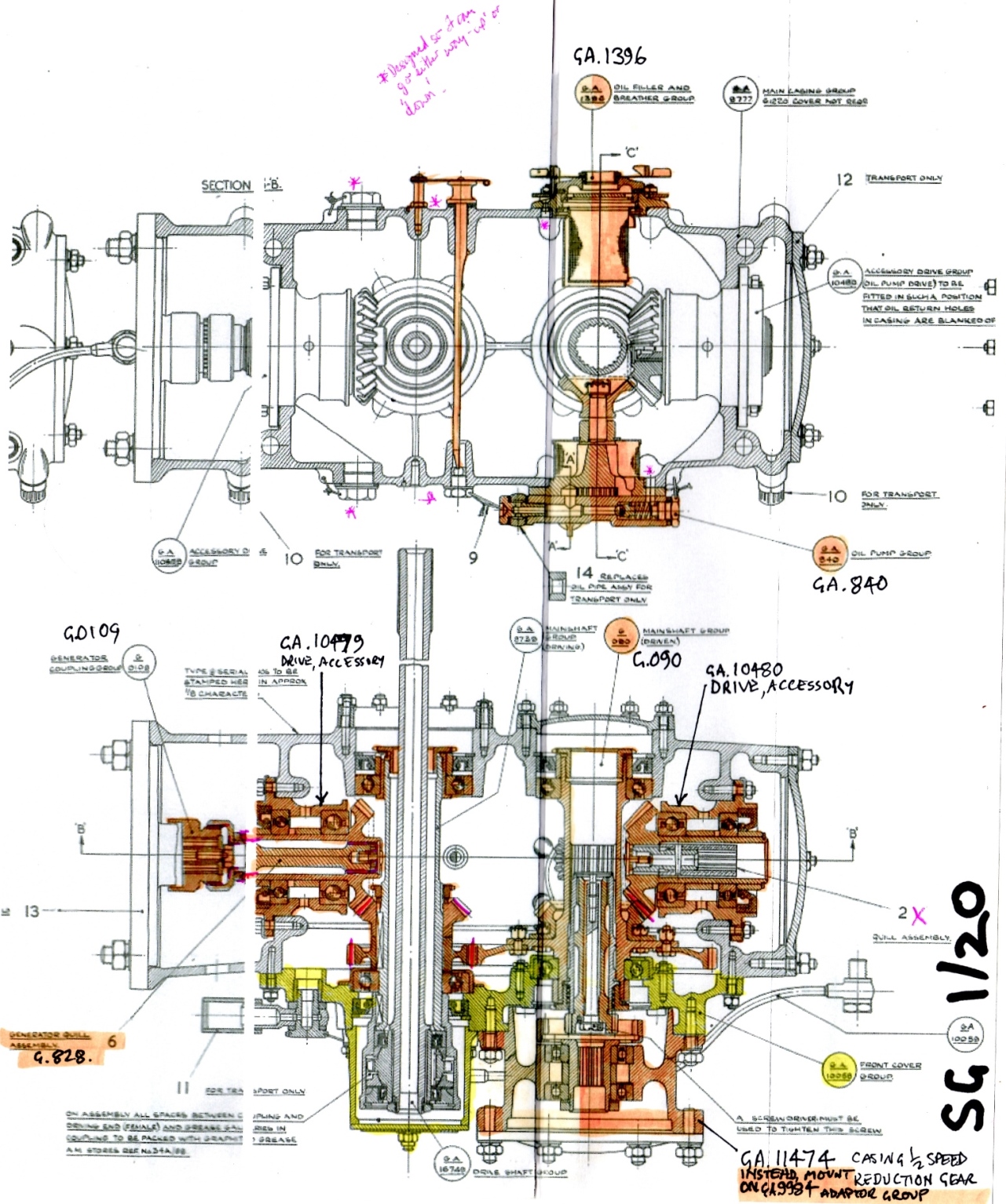
Like the early Vampire Mk.30 BFP I describe here, this panel reflects the World War Two era direct pitot-static systems for altimeter, ASI and rate-of-climb indicators, and vacuum-driven systems for the directional, artificial horizon and turn-and-slip gyro indicators. The vacuum or ‘suction’ for the latter three comes from a Pesco pump attached to the Goblin engine in the case of the DH.108 and Vampire F.I, and attached to the Rotol gearbox in the case of the Nene-engined Vampire Mk.30. The vacuum-driven systems were less effective at higher altitudes and were eventually replaced by electric gyro units. Vampire BFPs with electric gyro indicators are described here and here.

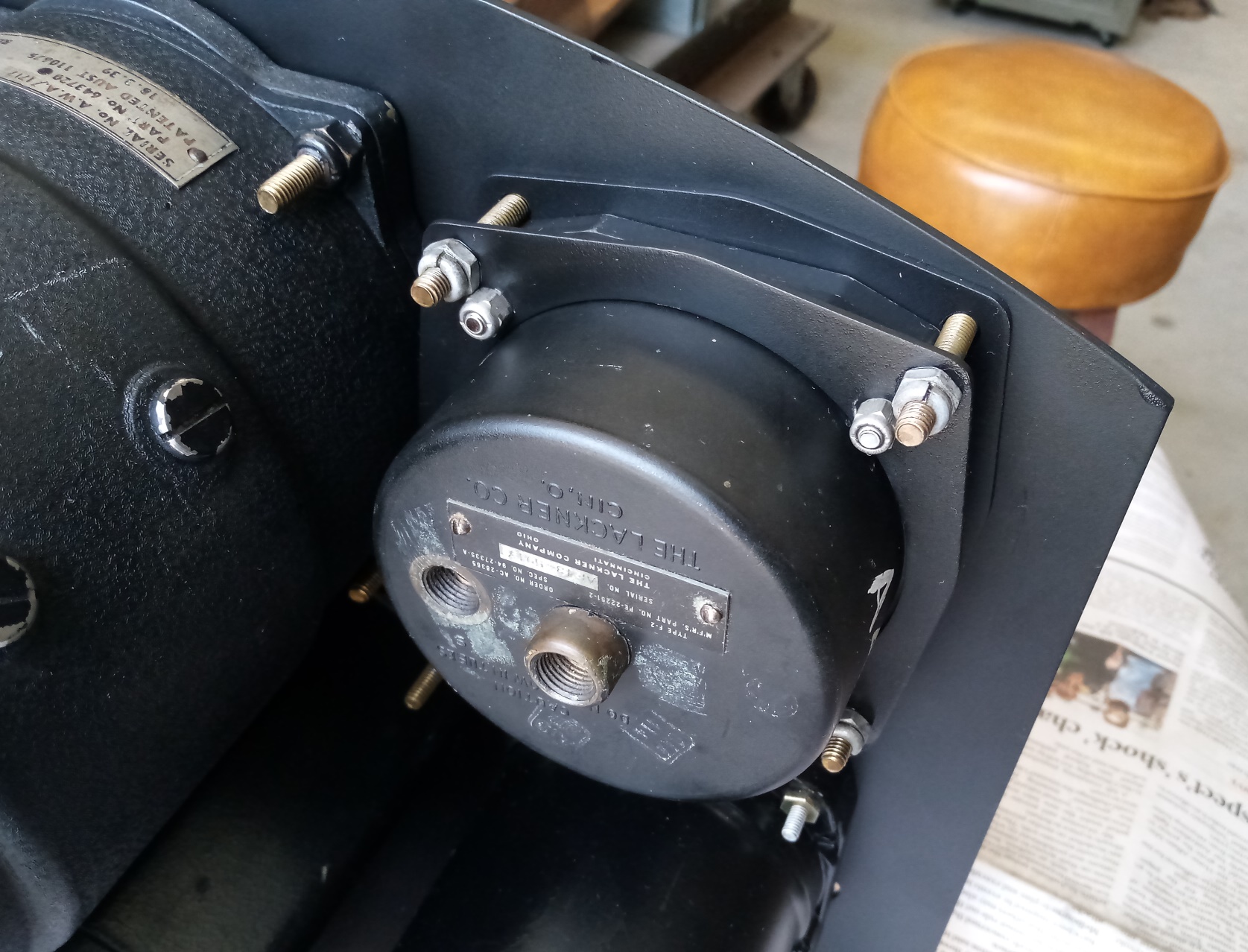
At this stage the whole panel assembly still needs a lot of work, with plumbing barely started – at the moment I just have the bare W.6216 suction box body – and leaving the mountings to a chance find for now.

1. Henry Matthews, DH. 108: The Saga of the First British Supersonic Aircraft, HPM Publications, Beirut, 1997

Thanks to David Collins for the instrument panel assembly drawing.

Preliminary Assembly of the Equipment and Gearboxes

Having a couple of KX generators and Lockheed hydraulic pumps, I figured I would attach these to the SG1/20 gearboxes to see how things come together. The generators for the Vampire Mk.30/31 are actually the KX-B and I haven’t seen any to date at all, let alone had the chance to acquire one. I bought these KXs because I thought they would help the cause one way or another. In addition, the KX was used on the DH.108, attached to the Goblin.

The hydraulic pumps I have aren’t quite right either. They should be Mk.VI, and I have one Mk.7 and one Mk.8. That probably wouldn’t matter of itself, but the orientations of the bodies have different clockings with respect to the mounting holes, presumably variations for specific applications.

Taking the transport covers off the pump locations revealed very clean interiors. Although there is a little black seepage, hopefully this is an indication that the oil seals have been largely effective in keeping the mud from seeping into the interior at the generator, driveshaft and compressor locations.

For two generator and two hydraulic pump locations there is only one quill and no couplings, so there is no check on engagement. However, this quick assembly shows the overall length of the arrangement, how it fits within the engine cowlings, and taught me a little more about the gearboxes and equipment. The trolley/stand I have built has also proven to be a good storage and work arrangement!

Blind Flying Panels – Early F.30

The intent of this panel is to represent the earliest configuration for the Australian-built single-seat Vampires, so I have matched the original schedule of spares as best I can. The original configuration is shown in the Pilot’s Notes and reproduced below.

The basic panel is one where I developed the dimensions myself a few years ago. I have since compared it with the original panels discussed in the previous posts, where I can, and am satisfied with the results. Areas are outside of the +/- 0.030” that might apply now for production parts and I can’t say that it would be as accurate as any panel made in the 40s or 50s – who knows! But that’s okay!

The panel is essentially a 6A/760 with a modified altimeter cut-out to accommodate the American C-12. I’ve also replicated the infill and adaptor parts to account for the change in size of the ASI, rate-of-climb and T&S.

While the adaption method for the T&S was straight forward, that for the ASI and ROC was not. This is because the pitch circle diameter (PCD) for the gauge and original panel are quite close. To attach the adaptor plate to the main panel first with screws and nuts would then mean no room for the mounting flange of the gauge. Indeed, for the ASI, the adaptor plate screws themselves come within a whisker of the gauge flange. This means either the adaptor plate needs to be tapped (and therefore needs sufficient thickness to retain the screws) or a second plate with inner and outer screw hole patterns needs to sit on the rear face of the mounting flange. This then has enough room for the nuts of both inner and outer sets of screws to turn, with the second nut in a pair having to be done up with an open spanner.

The ROC is even more complicated still! With the set screw in the bottom left-hand corner, there is no inner screw and the outer screw would need a tapped hole in the adaptor plate (as suggested above), and the screw cannot have any thread protrusion or it will clash with the mounting flange. This is because the flange extends much further out from the set screw location. Access to an original would be nice!

The exact reasoning behind the original design selection of the American gauges is not clear. I have not found any archival correspondence about it. Certainly, it would have been an economic choice to draw upon readily available wartime surplus stocks of new parts. It is not clear if shortages of items from the UK were anticipated, and even if they were, where a choice could be made between dealing with the problems as they arose during production or a design change to avoid the anticipated shortage. Irrespective of shortages, the redesign of the main electrical junction box with circuit breakers (American) in lieu of the original UK arrangement with fuses is clearly about extending a positive functional feature beyond American service aircraft. Items like the C-12 altimeter and C2 rate-of-climb were good choices as they proved to be enduring patterns.

Blind Flying Panel Mk.1G            6A/760

Air Speed Indicator AC-F2             G106A/50273-2

Artificial Horizon                               G6A/3182

Rate of Climb AC-C2                        1636-6A-B1

Altimeter C-12                                   671BK-010

Direction Indicator           AN5735-1, mfr’s p/n 646050

Turn & Slip                          G6A/3201

Blind Flying Panels – FB.31 A79-733

The second panel came to me with three instruments fitted – the A/H (installed upside down!), rate-of-climb and suction-driven T&S.

The three mods mentioned in the previous post that replace suction-driven instruments with electric units could be installed progressively. The G3 Compass system could be installed on its own, and was the first of the three modifications issued. The panel restored for A79-175 is actually indicative of this as the suction box attached to the back of the panel still has the open port for the artificial horizon.

The G3F Gyro Magnetic Compass system replaced the Magnesyn Remote Indicating Compass and Direction Indicator gyro; the new system being more accurate than the old. The suction-driven Direction Indicator is simply a gyro that needs to be set to something more accurate, and the performance of suction instruments degrade with altitude.

The artificial horizon mod – introducing the Mk.3 or HL5 – came second and required the G3 compass installation to either have already been installed or to be installed concurrently. With the change for the turn and slip coming later, deletion of the suction-driven A/H required, effectively, a low load for the vacuum system on start, and the union was modified with a pin-holed blank and gauze.

The electric T&S was introduced later, and this was when the entire vacuum system was deleted, including the Pesco pump mounted on the Rotol gearbox, and the suction gauge in the right-hand instrument panel.

Although A79-733 was modified for the electric T&S, I have restored this BFP with the suction-driven unit that it came with. I have a Hughes Mk.12 electric unit (marked ‘A79-472’, an aircraft that was scrapped at Tocumwal) which requires treatment of corroding magnesium alloy, which I will fit later to reflect the ‘all-electric’ status of ‘733.

Appendix A deficiency list from 8th October 1952 (NAA, Series MP287/1/0, Item 5077/26D) refers to the G6A/500032 ASI. For this panel I have installed what I have; the G6A/500148 has the same Smiths part-number. The obvious difference between the two parts is that the ’032 has a metallic case but the ‘148 has Bakelite.

This panel has the hole pattern for the ASI at around 45 deg. to the usual. The solid rivets used to fill the original holes are obvious. I am not certain that I have chosen the correct orientation for the indicator, but it does match the arrangement in A79-474 which I photographed in the late 1990s.

Air Speed Indicator G6A/500148, Smiths p/n 156AS

Artificial Horizon Mk.3    G6A/2717

Rate of Climb AC-C2         p/n 1636-6A-B1

Altimeter C-12                    G106A/500?? (poor condition behind a pretty face!)

Gyro Compass Indicator G3          G6B/500129, Kelvin & Hughes p/n V951

Turn & Slip                         G6A/3201, CAC Model No. J153 (made by Chivers)

Blind Flying Panels – FB.31 A79-175

In early 2021 I was lucky enough to acquire two original BFPs for my Australian Vampire FB.31s. I deliberated over which panel to allocate to which aircraft, eventually deciding based on the apparent history of each panel. The first panel I started work on I believe came from a spares stock. I believe this because it is of identical configuration and is marked with the same batch numbers as the BFP assembly put together by the Thomas family for A79-14. I think the panels were disposed from de Havilland Aircraft stocks at Bankstown.

The initial production arrangement of the blind flying panels for the RAAF single-seat Vampires were distinctive because they have the hole for the American altimeter (with adjust knob cut-out lower left) and for the AM type (adjust centre bottom). Some later panels, freshly cut, had the American altimeter trim only and the squarish holes for the G3F Compass indicator.

Having worked through the mod status of A79-175 based on what remains in the fuselage, the BFP needs to be assembled to suit. There are three main mods that had been incorporated that determine which gauges were used:

RAAF Mod 62/ DH Aust. Mod. V.175 – G3F Compass – Introduction

RAAF Mod 76/ DH Aust. Mod. V.159 – Sperry Mk 3 Type HL5 Artificial Horizon – Introduction

RAAF Mod 175/ DH Aust. Mod. V.191 – Electrical Turn and Slip Indicator Mk 2 – Introduction

The introduction of a power failure warning light (Mod 143/V.202) in the circuit for the G3F compass and HL5 artificial horizon is also applicable to A79-175 and requires the warning light on the BFP itself. However, I have decided not to fit the light now on the off-chance I come across another panel with the lamp holder hole before I need to install it in the aircraft… which will be in twenty years’ time, perhaps!

There were at least four ASI configurations for the Vampire F.30/FB.31 blind flying panel. The original fit was the American AC-F2 that was used in World War 2 types such as the P-40 Kittyhawk. It was then planned during single-seat Vampire production that this American type would be replaced with a Smith’s ‘safe-hand’ type that also had an inset Mach number in a small arc-window on the face of the gauge. Correspondence in the National Archives indicates there was a supply problem with this gauge, so it is not clear when they began to be fitted. When that ASI was introduced, the Mach meter in the left-hand instrument panel was deleted (but then reintroduced by Mod 74/ V.148 due to dissatisfaction with the inset indicator). Thirdly, RAAF Mod. 153, Inversion of Air Speed Indicator, was introduced. I don’t currently have a copy of the inversion mod, but I’m assuming that it is a simple inversion using the existing holes, as is the case in the unidentified test aircraft shown below. The fourth arrangement has the gauge mounted with holes at about 45 degrees to the usual pattern. It is not known what the mod number is for this version; it may well be an option or revision to either the safe-hand ASI introduction or inversion mods. It is not a commonly seen mod in existing panels, and some indications are that it was not introduced as the final iteration.

There were some mods on the RAAF single-seat Vampires that were not incorporated uniformly across the fleet, but having found that in general the late mods have been incorporated on A79-175, I assume that most if not all applicable mods had been incorporated; any mods where there is no remaining evidence either way, I assume the late mods were actually incorporated. A79-733 on the other hand, has evidence that several of the late mods were not incorporated.

The arrangement for panel then is the inverted ASI and the aircraft arrangement would include the appropriate Mach meter. Ideally at some point I will swap the A/H for an RAAF item and the T&S for an RAAF item without the unified threads – you can call me pedantic! And I need to correct UN screws to slots.

Air Speed Indicator (safe-hand)   G6A/500032, Smiths p/n 156AS

Artificial Horizon Mk.3                   6A/2717

Rate of Climb AC-C2                        p/n 1636-6A-B1

Altimeter C-12                                   CG Conn p/n 80.000

Gyro Compass Indicator G3          G6B/500129, Kelvin & Hughes p/n V951

Turn & Slip, Pullin Mk.2A              6A/3953/1

Starting on the Rotol Gearbox Path of Discovery

For years I have had a general knowledge of the SG3 Rotol Gearbox fitted to the Vampire Mk.30 and Mk.31. Years ago Alan Allen in the UK sent me a digital copy of the SG3/1 manual for the Nene Vampire and that was the starting point for learning more, but without getting my hands the real thing, I didn’t have good reason to get into the thick of it, having many other things demanding of my time.

In 2020 I had the chance to examine two SG1 gearboxes and make a simple comparison with the SG3/7. I knew even less about the SG1, so embarked on the process of figuring out their application. One had the data plate with Type ID on it: SG1/18. The other appeared to be identical. It turned out they were from the Gloster Meteor; the driveshaft pointing directly out of one of the main gearbox apertures plugs directly into the front of the Rolls Royce Derwent. The SG1/18 fits into the right-hand intake for the Derwent of some marks of the Meteor. This gearbox is set up to carry a generator – something like a Rotax KX, HX or 02 – and a Dowty hydraulic pump.

The original Vampire Mk.30/31 gearbox was the SG3/1 with the driveshaft located on a forward face, the other mounts were taken up by B3X Mk.III vacuum pump, KX-B generator, Hymatic compressor and Lockheed Mk.VI hydraulic pump. When the vacuum pump was deleted (by RAAF mod 175 or DHA mod V.191), the gearbox was modified as the SG3/7.

Comparing the SG3/7 illustration from the Vampire Mk.30/31 manual with the photos of the SG1/20 below, you can see how different the drive input is.

So having a need for a couple SG3/1 or SG3/7 gearboxes, I started to wonder about how common the SG3 and SG1 are – whether an SG1 would be a starting point for building an SG3.

After a little googling and looking at the various suppliers of scanned manuals, I found the AP.2240A Rotol Gearbox schedule of spares for the Meteor – from the very handy Aircraft Reports. Excellent!

Looking at the basics, it was easy to see that several of the assemblies that make up the SG1/18 are indeed common to the SG3s of interest. After trying to kid myself otherwise, it became obvious that the main gearbox cover is NOT common, although a cheat might be possible. BUT – what about the main casing itself? I’ll come back to that.

In November 2020 my friend Chris sent me an email with a photo of a ‘thing’ caked in mud and looking rather worse for wear, and asked ‘would I be interested?’ Well, that got me excited! He eventually managed to source two SG1/20 gearboxes for me!

So what’s the SG1/20? Similar to the SG1/18, but, importantly and usefully, also carries the set-up for the Hymatic compressor. It was fitted in the left-hand inlet of some Meteor marks.

The basic drive assembly for the compressor is common to the SG1/20 and SG3, but the SG3 also has a mounting adaptor because of the different location on the gearbox where it is attached.

By working through the parts lists for the SG3/1 and SG1/20 and the section drawings for each, I have been able to show that there are a lot of common drive assemblies plus the oil pump, and other parts. This is shown in the drawing below.

Orange highlights: common parts; Yellow – the cover that doesn’t match; No highlight – not sure!

Are the main casings the same? They certainly don’t have the same part number. But the main attachment bolting pattern matches and given how the various assemblies fit, I think the casing of the SG1/20 will work for the SG3. It is clear that Rotol introduced design improvements over the years but retained commonality, and it is also apparent that the casings often have bosses in the casting that may or may not be in use for a particular assembly. I think it is likely these casings will do the job.

It wasn’t until mid-June this year that I picked up the gearboxes. First thing: Clean and protect!

The suggestion was to start with high pressure water but I was worried about the water getting inside. I took the 3 hour per gearbox gentle clean instead! This is exterior only – will need to do something about the interior after lockdown – just an inhibit of sorts as I won’t be disassembling until I actually have what I need to make at least one SG3. Below are a couple of photos – one gearbox before cleaning, and the two after.

There is no Mystery of the Missing Generator

About time I put this one to rest. The answer behind this puzzle is that the generator was there. Past tense! I just didn’t know what the guts of one looked like. I didn’t understand that there are the remains in the photo, and I had been put off the scent by the state of the Rotol gearbox fitted to Camden Museum’s A79-14. This gearbox has a blanking plate over the generator position and the Dunlop pressure reducing valve (AHO19682 – for the Canopy Seal line) and its mounting bracket (L002109A) attached on the blanking plate, as if the blanking plate should be there for a serviceable aircraft. (Although I would certainly mount the bracket over the blanking plate if I had just removed the generator – to keep it all together.)

The Generator position on the gearbox of A79-14

Below is the image from AP.1095C Vol.1, Sect. 5, Chap.9, that made me see the light. Notice the long bolts that run much of the length of the generator, holding the casing and mounting together. This is actually for the KX, but is much the same for the KX-B.

A79-536: Now that I know…

Air Diagram AD 4551 and Junction Box 1

In an effort to identify modifications incorporated in to Vampire FB.9 R1382’s Junction Box 1, I went searching for a later revision of Air Diagram AD 4551. We already had issue 3; this came from Gina’s Vampire library. My general Google search came to nothing. Not really surprised!

I found a reference using NAA RecordSearch to ‘Vampire FB Mark 5 Electrical Installation’ by chance while I was having a look for something else on Vampires. The FB.5 and FB.9 are largely the same, the essential difference is that airconditioning (an ACRE 8 cold air unit) is fitted to the FB.9. I imagine that this file is in the Australian archives because the RAAF had a single Vampire FB.5, A78-3 (formerly RAF registration VV465).

So I ordered a digital copy in February; the order cost just under $40 including GST and took 12 days to process. That copy is available at the NAA here:

http://RecordSearch.naa.gov.au/scripts/AutoSearch.asp?Number=3398245&O=I

So it turns out that the file contains AD 4551 Iss. 3. The AD 4551 pages are scanned at a suitably high resolution and overall the result is very clean. I had a look through this just to make sure that Iss. 3 was Iss. 3! Apart from the NAA version not having some small hand mark-ups that our copy had, I didn’t see any edition differences.

When working through the Gun Firing circuit to convert this in to a wiring/routing diagram for Junction Box 1, I had trouble reading some pin IDs on our version. The hardcopy in Gina’s library is a bit tatty (some tears) and grimy; also in the original photographic repro process, the pages weren’t flat so some of the schematic is blurry.

Gun Firing circuit scanned from Gina’s version of AD 4551.

The GF circuit from the National Archives file.

So I took a look at the NAA version to see the pin ID and found a lot more than what I was expecting. There was in fact a significant difference in the actual circuit. The version we already had included Mod 3146. Looking at the circuit diagrams you should be able to see that they are fairly different. There may be other differences too, in other circuits. No idea yet if this was a relevant discovery for R1382, but at least the NAA file is now there for anybody who is interested or may find it useful!

Alternative Fuel Gauge Panel

Five years ago I saw a photo that showed a rather unusual single-seat Vampire fuel gauge panel. The regular panel, when you look at the front face of it is mostly just gauges, placards and the base panel which is made of Tufnol – fibre reinforced phenolic.

This mystery panel had been seriously messed with! The top line of gauges now sat in a folded aluminium part that was attached to the Tufnol. This component in itself didn’t make for a bad looking assembly, but overall it was rather rough looking.

What was this assembly? I thought it was a rough repair, but why so complicated? Why not just replace the panel!

Turns out there were two mods involved. Firstly (RAAF mod 160, DH mod V.204) the Mk.II 8-day clock was replaced by the V.308 stopwatch clock, with the centre fuel tank gauge moving to the old clock position, and the new clock being installed in the centre-top position. The folded aluminium part was required to reinforce the Tufnol that had been dramatically weakened by the much larger hole for the clock, and to provide sufficient space for it.

Somebody didn’t like that idea, so the larger clock was then moved over to the right hand instrument panel, and the centre fuel tank gauge was then moved  back to its original position. (RAAF mod 231, DH mod V224.)

I think that most aircraft bypassed this mess, with the larger clock immediately being installed in the RH panel, as the aircraft came in for servicing and mods.

However, it turns out that A79-14 is a case that was fitted with the mongrel panel (not the panel I originally saw); see the photo below.

Although I still don’t understand why the original panel wasn’t replaced during either mod, given how much work I imagine was involved, I think it is nice that this oddity is preserved. Perhaps for some lessons on how things should have been done properly the first time (new clock in RH panel straight up), or otherwise on the diversity in modifications in our remaining Australian-built single-seat Vampires.

Vampire arrives

On Wednesday 24th May, Vampire R1382 arrived to join Australian-built Vampires A79-175 and A79-733.

IMAG6112 cr br co sml

Thanks to Gina and the guys at Steve Holland Transport and Turner and Central Cranes.