Blind Flying Panels – FB.31 A79-733

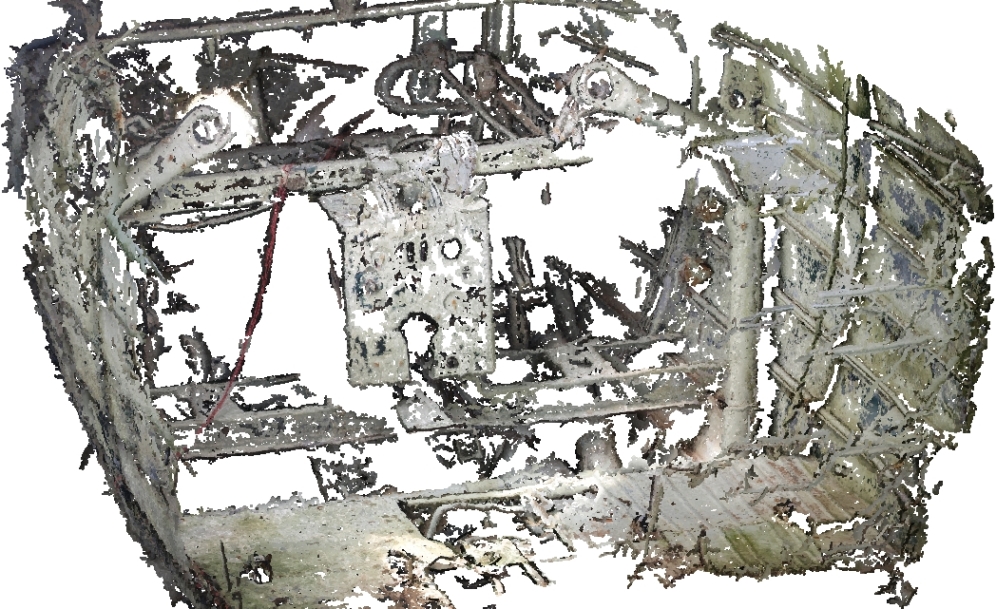
The second panel came to me with three instruments fitted – the A/H (installed upside down!), rate-of-climb and suction-driven T&S.

The three mods mentioned in the previous post that replace suction-driven instruments with electric units could be installed progressively. The G3 Compass system could be installed on its own, and was the first of the three modifications issued. The panel restored for A79-175 is actually indicative of this as the suction box attached to the back of the panel still has the open port for the artificial horizon.

The G3F Gyro Magnetic Compass system replaced the Magnesyn Remote Indicating Compass and Direction Indicator gyro; the new system being more accurate than the old. The suction-driven Direction Indicator is simply a gyro that needs to be set to something more accurate, and the performance of suction instruments degrade with altitude.

The artificial horizon mod – introducing the Mk.3 or HL5 – came second and required the G3 compass installation to either have already been installed or to be installed concurrently. With the change for the turn and slip coming later, deletion of the suction-driven A/H required, effectively, a low load for the vacuum system on start, and the union was modified with a pin-holed blank and gauze.

The electric T&S was introduced later, and this was when the entire vacuum system was deleted, including the Pesco pump mounted on the Rotol gearbox, and the suction gauge in the right-hand instrument panel.

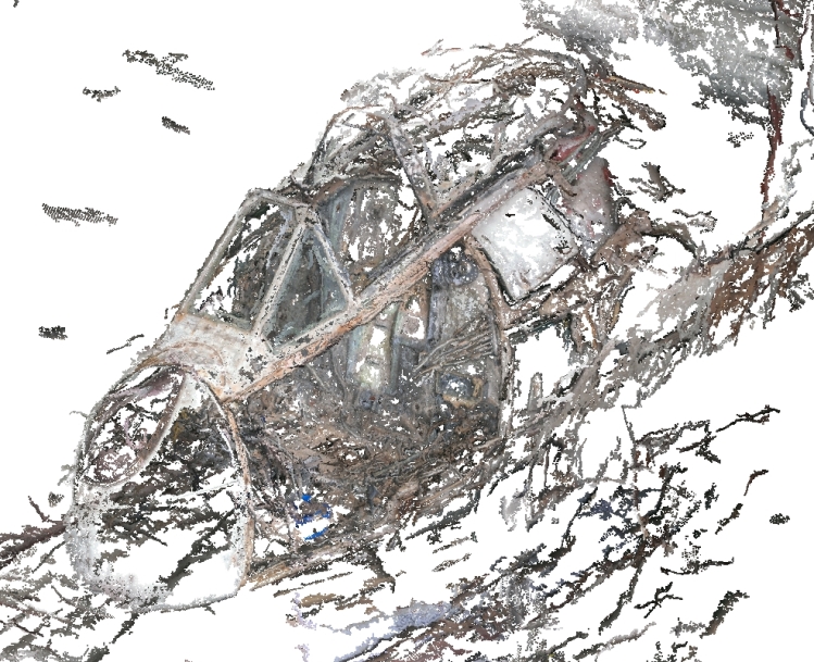
Although A79-733 was modified for the electric T&S, I have restored this BFP with the suction-driven unit that it came with. I have a Hughes Mk.12 electric unit (marked ‘A79-472’, an aircraft that was scrapped at Tocumwal) which requires treatment of corroding magnesium alloy, which I will fit later to reflect the ‘all-electric’ status of ‘733.

Appendix A deficiency list from 8th October 1952 (NAA, Series MP287/1/0, Item 5077/26D) refers to the G6A/500032 ASI. For this panel I have installed what I have; the G6A/500148 has the same Smiths part-number. The obvious difference between the two parts is that the ’032 has a metallic case but the ‘148 has Bakelite.

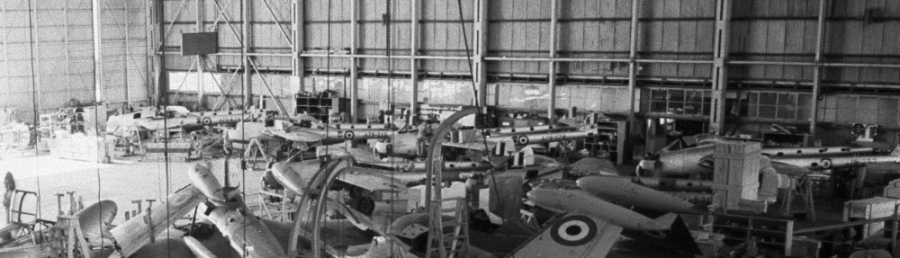
This panel has the hole pattern for the ASI at around 45 deg. to the usual. The solid rivets used to fill the original holes are obvious. I am not certain that I have chosen the correct orientation for the indicator, but it does match the arrangement in A79-474 which I photographed in the late 1990s.

Air Speed Indicator G6A/500148, Smiths p/n 156AS

Artificial Horizon Mk.3    G6A/2717

Rate of Climb AC-C2         p/n 1636-6A-B1

Altimeter C-12                    G106A/500?? (poor condition behind a pretty face!)

Gyro Compass Indicator G3          G6B/500129, Kelvin & Hughes p/n V951

Turn & Slip                         G6A/3201, CAC Model No. J153 (made by Chivers)

Photogrammetry III

In 2016 I was starting to build a detailed understanding of all of the Vampire’s wooden structure. The exact build up of the structure at the tight little area between the aft of the Duct cut-out and Bulkhead 4 (the firewall) was unclear to me. The build is compound with the various laminates being built up in different directions – circumferentially around the cut-out, circumferentially around the fuselage, and with differing cover plies according to how much room was available. This gave rise to an exercise in determining the amount of detail that can be captured with VSFM in a portable 3D expression – meaning that I wanted to be able to study the structure when I wasn’t in the shed with the Vampire. The result was excellent! By this time I had become realistic about the computing power required to complete large photogrammetry tasks. I now had a workstation with an Nvidia K620 GPU. This made mole hills out of mountains!

Detail study: the left-hand Duct cut-out, Vampire A79-733

Detail study: the left-hand Duct cut-out, Vampire A79-733

My first jobs for 2017 were an entire detail shoot of the fuselage of A79-733 and a detail shoot of A79-175’s RH instrument panel in-situ. The purpose of these shoots is a true test of the potential use of this data in CAD.

3D cloud of points created from around 660 photographs of the fuselage pod of A79-733

3D cloud of points created from around 660 photographs of the fuselage pod of A79-733

Detail study: the right-hand instrument panel and surrounds in the cockpit of A79-175

Detail study: the right-hand instrument panel and surrounds in the cockpit of A79-175

Photogrammetry II

My next project was an initial pass through the interior of Camden Museum of Aviation’s GAF Lincoln Mk.30A cockpit/forward fuselage section. This is a large and complicated structure and I simply did not take enough photos to produce a point cloud that would get people excited! There were two issues with the result. Firstly, VSFM can run out of information to connect all photographs – simply, there are not enough photos to put everything together. The result is multiple reduced recreations that represent local features of the full object. Each point cloud, whether a successful result of the entire object, or of a fractured, is called a model. The result for the Lincoln was nine models.

Some of the separate models generated from the Lincoln photographs

Some of the separate models generated from the Lincoln photographs

Visiting Albury in 2015, I took a series of 52 photos of the interior of DC-2 A30-11 – the aircraft painted as Uiver. This was a rushed effort but I felt the result showed potential.

The cockpit of the Albury DC-2

The cockpit of the Albury DC-2

Photogrammetry I

Since 2014 I have been researching and trialling photogrammetry as an aid in rebuilding the fuselage of Vampire A79-733. My efforts have only been sporadic due to my usual lack of focus and other priorities.

My first photogrammetry used Autodesk 123D. I was also thinking about possibilities for 3D printing. Starting with something simple, I chose a TR-1936 controller because I wanted to make a mockup of a TR-1520 controller – the latter seems to be made of unobtanium. From a reverse-engineering point-of-view, this was not a particularly good idea; the boxes are very simple and the obvious method would be to get out the ruler and just measure up or even just cannibalise a 1936 unit. Starting with something simple was all that lay behind it. I had already done a fair bit of reading about photogrammetry so was aware of object characteristics that are unhelpful to the process. This simple test highlighted these issues. The controller I used was of very good condition and was very clean. The controller has plenty of reflective surfaces; the Perspex of the dial window, the nice fresh knob, the glossy lacquer over the ink mod markings and even the overall black paint. The basic photogrammetry process relies upon many unique features to triangulate upon. A uniform surface – the smooth black paint – is a ‘large’ expanse of nothing to triangulate. A glossy surface reflects and may just transfer ambient diffuse light to the camera lens or a reflection of something beyond in the area that surrounds the object. The Perspex of the channel dial may send light or a reflection of something beyond to the camera, or the camera may see the characters of the dial itself, or in one photograph, we might see a combination of both. Seeing different things from different angles ‘does not compute’. Depending on the software, it may present the initial result with holes or it may have some means of creating infill.

The TR-1936 controller with 123D was a disaster! Knowing the limitations, I then created a 123D project using a ‘Bug’ by artist Mark Brown. This was initially very successful, but then I made one mistake. Fatal. And in 123D there is no undo. I lost most of the job which had been very tedious. While I wanted to take the project  to completion, working on the cloud started to be a problem and I gave up out of frustration. 123D is targeted at 3D printing and has a strong infill capability. I quickly decided that 123D was not for my main project and went elsewhere.

123D result of Mark Brown's Xmas Drone (2004) using 28 photos

123D result of Mark Brown’s Xmas Drone (2004) using 28 photos

I had previously looked at VSFM by Changchang Wu, that has CMVS by Yasutaka Furukawa built in through the user interface, without making any real progress. This time I ran photo series of Mark Brown Bugs. The results were ordinary only, but I could see that this was because of the quality and quantity of photographs I used, and because of the plain white-wall background to the photos.

Sometimes I become impatient. This was one of those times. I decided to leap in the deep end. I took 100 photographs of the fuselage of Vampire A79-733. Without too much fuss – just some memory problems and 17+ hours of my business-type laptop grinding away – I got a an impressive outcome. See below.

Dense point cloud reconstruction of A79-733's fuselage using VSFM and CMVS

Dense point cloud reconstruction of A79-733’s fuselage using VSFM and CMVS

After that success, I created a point cloud of a Rolls-Royce Nene Mk.103 from 170 photos. My Laptop struggled a great deal from this load; VSFM stopping several times as it ran out of memory. This was not such a big deal as VSFM stores its work as it goes, so on starting a run again, it resumes processing from where it crashed.

Rolls-Royce Nene Mk.103

Rolls-Royce Nene Mk.103

I saw these runs as a way to learn to use the software and to see what it could do; to see what I needed to do to make it useful.